Techniques


Cameras

I use monochrome video cameras from "The Imaging Source" and image through my 9¼" Celestron telescope (see About).

The 'wide field' DMK 41AU02 (1,280 x 960 pixels) is usually used with an Astronomik red-pass filter and very occasionally an Astronomik IR-pass filter. The reasons for imaging in red and infra-red (IR) light are outlined below. This camera is good for recording fields >100 km across, allowing smaller lunar features to be shown in context, or to capture larger features. It is used at its maximum frame rate of 15 fps with exposure times faster than 1/30 sec. The DMK 41AU02 uses Sony's ½" (8.0 mm) ICX205AL CCD, with 1,228,800 4.65 x 4.65 µm² pixels and 8 bit dynamic range (256 grey tones). As shown to the right, the CCD's peak sensitivity is in the blue-green region (500 nm) with a quantum efficiency of ~45%. The performance in red light is good, but relatively poor in the near infra-red.

The more sensitive DMK 21AU618 (640 x 480 pixels) is used with either an Astronomik IR-pass filter or the red-pass filter for imaging fields under 100 km. The camera can operate at up to 60 fps. The DMK 21AU618 is based on the ¼" (4.5 mm) Sony ICX618ALA CCD, with 307,200 5.6 x 5.6 µm² pixels and 8 bit dynamic range. The CCD is most sensitive to red light and also very sensitive to near infrared. With quantum efficiencies of 62% at 600 nm and 50% at 800 nm, the camera is often capable of exposure times of 1/100 sec in either red or infra-red. Both cameras are capable of resolutions down to 1 km on the Moon.


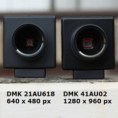
Imaging in Red & Infra-red (IR) Light

Though the Moon is essentially a black-and-white object, imaging in white light will not give the best results due to atmospheric refraction. At high magnifications, colour fringing caused by atmospheric refraction is quite apparent. Blue light (450-480 nm) is more strongly refracted than red light (620-700 nm), with the effect increasing with decreasing altitude above the horizon. Light is also scattered by molecules and dust in the atmosphere, which is a separate effect. Blue light is far more strongly scattered than red light, hence the blue colouration of the sky. So even under good seeing conditions (i.e. minimal turbulence), an image captured in blue light will look less sharp than a red image.


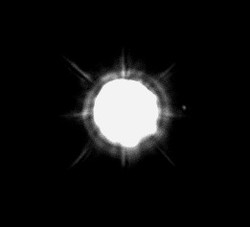
Atmospheric turbulence results in rapid variation in refraction, causing stars to “twinkle”. The underlying cause is rapid variation in air density hence the refractive index of the air column through which the starlight passes. Due to turbulence, at high magnifications the Moon appears to have a rapidly moving, “boiling” surface. This is simulated in the animated GIF (left), built from 10 consecutive aligned frames. This was recorded in red light under good seeing conditions; far less detail is visible under typical or poor conditions. Turbulence is far less disruptive to red light than blue light, and near infra-red light (700-1000 nm) is even less susceptible to atmospheric effects.

Fortunately some “black-and-white” CCD chips are very sensitive to red and infra-red light, allowing imaging at wavelengths that are least affected by the atmosphere. Under perfect conditions (no atmosphere), the resolving power of a telescope (R) should be better in blue light (450-480 nm) vs longer wavelength red light (620-7000 nm) with R (in arcseconds) = 0.21×λ/D, where λ = wavelength in nm and D = telescope aperture in mm. But in practice red outperforms blue in most cases due to the atmosphere. There are many quality filters that allow isolation of selected wavelengths (colours) of light. I use either an Astronomik Red type IIc filter (~580-670 nm, >95%) or Astronomik ProPlanet 742 IR filter (742-1100 nm, >95%) and present processed images in black-and-white. Lunar features show more tonal variation in red than in infra-red light. Lunar ray systems in particular are much more distinct when imaged in red light. In general, if seeing is good, the red filter will deliver better resolution than the IR filter.


Video Imaging

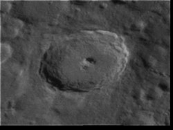
Rather than record a single image, the DMK cameras are used to record AVI files, which contain thousands of images. This data is then used to construct a single image. There are two main reasons for doing this. The first is to overcome atmospheric turbulence. Even at 1/60 sec exposures, the majority of individual images will be blurred or otherwise distorted by the atmosphere. However up to 8% of images will be good, with a handful of excellent images - they just have to be identified. Typically I would record ~3,500 images and select only 250-300 of the best images for further processing. As an example, the three images below are the best (left), median (centre) and worst (right) frames from 120 images of crater Tycho captured over a 2 second period.
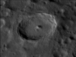
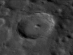
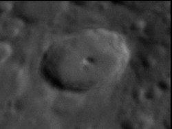
Best frame from 120 framesTypical median frameWorst frame from 120 frames


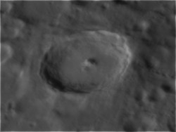
The second reason is that "stacking", the process of aligning images on common features and then summing or integrating the images to give a single consensus image, results in impressive levels of image enhancement. This is due to improvement in the signal-to-noise ratio (S/N), allowing subtle details to rise up out of the background noise. (S/N ∝ √n, where n = number of stacked images.) Processed images of Tycho derived from a 4,000 frame AVI illustrates the point below. The single best frame from 4,000 (left) is clearly sharper than the best frame above, and an image constructed from the 16 best frames is even better (centre). The best 256 frames gives a composite image that contains a high level of detail and very little noise (right).
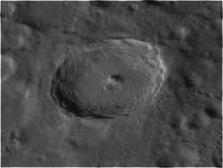

Best frame from 4000 framesBest 25 frames (from 4000) stackedBest 256 frames stacked


But rubbish in, rubbish out - a subset of good images is required for best results. The image to the left was constructed by stacking all 4,000 frames and the fine detail is lost. Further image improvement can be made by careful use of image processing techniques such as wavelet manipulation, unsharp masking, blurring to remove noise, etc. Over-processing can however introduce artifacts. The registration, quality rank ordering, stacking and wavelet manipulation of individual images in AVI files can be performed by Registax, one of the most powerful and impressive image processing software packages around. And it is free.

All 4000 frames stacked - poor result

In older versions of Registax the user would select a good quality reference frame and the alignment point(s). Whilst the software did a good job rank ordering the images by quality, I would also manually go through 200+ images, discarding some before stacking. With a single core processor a large AVI could take 20 min to align. Registax 6 entirely automates the process, including the automated selection of hundreds of alignment points. Whilst some parameters can be altered, basically the user selects the number of frames to stack and the software does the rest. With powerful multicore processors, image processing is completed in minutes and the results are better than manual processing with Registax 5. Consequently I reprocessed my older images with Registax 6. Here is a high quality image of Tycho with detail to 1 km, built from 270 images software-selected from 3,500 by Registax 6, recorded with the DMK 41AU02 in red light.


Image Scale and Resolution

In capturing an image on the CCD chip, a "continuous" analogue image formed by the telescope optics is recorded as a set of "discrete" digital signals by the pixel array. If too few pixels are used, hard won detail is thrown away. If the signal is spread over too many pixels it becomes weak and detail is compromised due to longer exposure times. The animation shows 50 × 50 pixels taken from five good AVI frames. This is Tycho's central mountain region, blown up to show how details at the limit of resolution are spread over several pixels. Averaging these good frames gives a high quality image. So how many pixels? According to the "Nyquist" sampling theorem, a signal can be accurately reproduced provided the sampling rate is at least twice the maximum frequency in the signal. In plain language, the image must be projected at a scale where the limit of resolution (as a linear dimension) exceeds the width of two pixels.


There are several measures of telescope resolution, but a good practical guide is Dawes' limit, empirically derived from double star observations in the 1800s by William R. Dawes. For my 9¼" (235 mm) Celestron, Dawes' limit = 0.49". However unless you live in a special location such as Mauna Kea, the atmosphere itself limits resolution to ~0.5" (0.00014°) and only fleetingly. More often >1" is the best that can be achieved except for rare occasions. A 0.5" limit of resolution allows lunar detail down to just under 1 km to be discerned; the Moon has a diameter of 3,474 km and an average angular size of 1,890".

An analogue image with 0.5" resolution requires sampling at a scale of 0.25" or less. For the image scale of 0.5" to exceed two pixels, the projection scale must be at least 22.4 µm/arcsecond for the DMK 21AU618 and 18.6 µm/arcsecond for the DMK 41AU02. A further consideration however is signal noise inherent in the electronics, which occurs on a single pixel scale. The impact of noise can be minimized by blurring or averaging neighbouring pixel values. When a larger image scale than the minimum suggested by sampling theory is used, this method of noise reduction tends not to damage 'real' detail. In practice I have found an image scale of 6 pixels per arcsecond works well. This is achieved for the DMK 21AU618 and DMK 41AU02 using a 3x Televue® barlow lens and a 2.5x Televue® Powermate respectively.
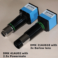
  

Visual Observing

On the few occasions that I opt to observe the Moon visually, I use high quality eyepieces with long eye relief. My favourite is a 10 mm Televue Radian, which gives a magnification of 235× and apparent field of 60°. When seeing is very good, I sometimes use an 8 mm Radian (294×). For the reasons outlined above, a yellow filter such as a Meade 4000 series #12 filter can improve image quality by cutting out the blue end of the spectrum. Observing the Moon's surface on the computer screen using the DMK 41AU02 video camera and a red filter is also a very nice high magnification approach provided the seeing is good.

Imaging Tips


There are many excellent astrophotographers posting on the internet. No doubt each has spent countless hours selecting and refining their equipment to get the best possible results. My own refinement program is ongoing. I set the goal of having my telescope and cameras ready to capture quality images within 3 minutes on any evening if I want to do astrophotography. I can also completely pack up in less than 5 minutes. Whilst equipment and techniques vary according to the type of astronomical target, attention to the following points will benefit all types of night-time astrophotography.

Equilibrated Equipment: It is crucial that all optical equipment is at thermal equilibrium with the outdoor environment. This is best achieved by storing the telescope with all equipment including cameras fitted in an outdoor observatory. I have fitted two 12V maglev 80 mm fans to the rear of the mirror cell to assist in cooling the optical tube assembly - I have not cut any holes in the main tube! I think it helps to have the observatory partly sheltered, in my case by fruit trees. It is best that the observatory is not made of a material that retains heat from the day, hence creating problematic air currents at night. A brick or masonry observatory is particularly prone to this problem. A roll off observatory is less likely to create warm air currents around the telescope than an enclosed structure such as a dome. The heat from my body can be enough to disturb high magnification images so I sit away from the instrument. Rubberized floor mats improve the comfort of standing/sitting out in the cold, as well as minimizing damage if any equipment is dropped.

Collimation: A great instrument will produce bad images unless it is well collimated. I test collimation on real stars located near the ecliptic, the path followed by Moon and planets. I prefer the original Phillips head bolts (vs "Bob's Knobs") in the secondary mirror cell and use a small engineering screwdriver whilst looking at the image on screen - the DMK 41AU02 is a great tool for collimation. An advantage of the fork mount over a German mount for the Schmidt Cassegrain Telescope (SCT) is that the telescope is never reversed, hence turning the primary mirror over by 180° and potentially shifting the mirror. STCs are known for mirror flop, which ruins critical collimation. I modified my 9¼" telescope to eliminate this problem. Using a steel spark plug feeler gauge set, I measured the gap at several points between the primary mirror and central baffle tube in various orientations. A gap of up to 300µm was measured in some positions and it would vary slightly as the tube was moved - the main source of the "mirror flop". An aluminium foil shim (300µm thickness)was shaped to precisely fill the gap, totally eliminated mirror flop without introducing any distortion. The optics are excellent, the telescope can split Sirius A-B when seeing is good. Sirius B, a white dwarf, is the tiny point of light to the right of the main star.


Focus: Sharp focus is everything. The standard focusers on most commercial SCTs do not give the fine control required for very high power observing. I replaced the standard unit with a Feather Touch® microfocuser from US company Starlight Instruments. It provides a 1:10 fine focus dial. The focuser thread is also cut to give a tighter fit than is typical. I have found that critical focus comes within a quarter turn of the microfocuser ~ 1/40th of a turn of the regular focuser. I have also fitted a small geared servo motor that drives the microfocuser very slowly and smoothly via a removable rubber belt. Focus needs to be periodically adjusted as the telescope cools at night. Focus for photography is determined by the on screen image, not through the eyepiece (though they are set to be parfocal).

C9.25 vs C11: I chose the 9¼" Celestron C9.25 over the 11" C11 as it is widely reported to come to equilibrium, i.e. cool down, significantly faster than the larger instrument. The cool down time is similar to my C8 (Celestron Ultima2000). The C9.25 has other advantages over the C11. The field in the C9.25 is noticeably flatter than in either the C8 or C11 as it is designed around an f/2.3 primary mirror rather than a "faster" f/2.0 mirror. This probably has little impact on narrow field imaging but certainly makes wide field imaging and viewing more enjoyable as correct focus is achieved over a much wider area. Perhaps more importantly the longer focal length provides more leeway in the precise collimation of the C9.25. The smallest turn of the collimation screws gives an observable change, and excellent collimation is critical. The C11 is also known to be more prone to image shift and mirror flop than the C9.25, which in extreme cases plays havoc with collimation and image centration. In my case I was able to minimize both to the point were they are not noticeable even at very high magnifications. Whilst the CPC equatorial fork mount copes with the C9.25, the heavier C11 is probably pushing this arrangement. The C11 certainly collects more light than the C9.25, but this is not a significant advantage for bright objects like the Moon. In theory the C11 should have better resolving power than the C9.25, but this does assume accurate collimation, focus and thermal equilibrium. At any rate, on most evenings the resolution of either is limited by the atmosphere rather than the optics.

Camera Settings: Attention to camera settings is crucial. For background, the CCD sensor chip is made up of an array of pixels, where each pixel is essentially a light sensitive capacitor that builds up a charge proportional to the number of photons that strike that pixel. If one electron was registered for every photon, that would represent a "quantum efficiency" of 100%. The DMK 41AU02 CCD chip (Sony ICX205AL) has a maximum quantum efficiency of 42% at 480 nm. Each pixel has a maximum electron holding capacity beyond which it cannot collect further information. So the camera should be used in such a way as minimize the number of fully saturated pixels or else those parts of the image are burnt out and lacking detail. The Sony ICX205AL has a well capacity of up to 10,200 electrons per pixel - that level represents white. The electronics have an inherent read noise, in this case 10 electrons (RMS), meaning that neighbouring pixels must differ by at least twice this figure to be able to be differentiated. Consequently the camera digitizes each pixel output into 8 bits, giving a 256 level grey scale. The CCD raw output is linear, which is very convenient.

The image capture software IC Capture (Imaging Source) shows a histogram that presents the distribution of light intensities recorded by the CCD per exposure across the 256 level grey scale. This tool is essential for setting up the two most important and inter-related camera settings: Exposure (time) and Gain. In order not to have parts of the final image burnt out and to allow for some head room during image processing, the vast majority of maximum pixel values should not exceed grey scale value ~190, i.e. 75% on the histogram. Images recorded where maximum histogram values fall well below 50% will tend to be too dark and lack in detail. This balance can be achieved by adjusting both Gain and Exposure, with increasing Gain allowing for shorter exposure times. Ideally Exposure should be faster than 1/60 sec. Faster times increase the proportion of "good" frames that overcome atmospheric effects. The number of good frames decreases dramatically when exposure times slower than 1/30 sec are used. Gain is a linear function that proportionally increases the pixel signal, allowing for shorter exposure times. In the case of the Imaging Source cameras, Gain ranges from 260 - 1023, with each step of 152 units doubling the signal strength. Gain appears to increase camera sensitivity, but it doesn't as both signal and noise are amplified in proportion. Too high a Gain setting results in a poor quality "noisy" image. Gain is analogous to ISO setting on a DSLR camera, though harking back to film camera convention, the linear steps in ISO follow the sequence 100, 200, 400, 800, etc. The inherent noise in the DMK cameras can be noticeably improved by cooling the camera to below 0°C, allowing higher Gain settings (hence shorter exposure times) to be used. This involves modifying the camera - I won't go into those details here.

Brightness and Gamma are two other camera parameters that can be adjusted but are best permanently set to specific values. Brightness simply imparts an equal signal increase to all pixel levels, so it should be left at "0". Gamma is a non-linear function that can emphasize differences in dark tones whilst compressing light tones or visa versa. It is best to leave Gamma set at 100% (i.e linear) for image capture to avoid unintended signal compression hence loss of data. Gamma and other similar algorithms can however be useful when applied in the final image processing steps.

Dust: Every speck of dust that makes its way onto the CCD creates a big black spot in the images. Consequently the DMK cameras have been rigorously cleaned and sealed against dust with an Astronomik MC-clear filter, which has a high transmission in visible, UV and IR light. The electrostatic nature of the CCD attracts dust particles and they can be hard to remove. Dust particles on other parts of the optical train are of less concern. The Imaging Source website has some useful information on CCD cleaning.

Dew: Dew is the bane of all astronomers. A beautiful evening and the optics are covered in condensation. Whilst there are a number of commercial anti-dew heaters, I gave very careful consideration to what is required. In the SCT design, the primary and secondary mirrors are well protected, however the glass corrector plate at the front end of the telescope is notorious for collecting dew. Without any protection the corrector plate cools to slightly below air temperature and collects condensation from the air. A "heater" is used to slow the rate of cooling of air within the sealed SCT so that the corrector plate remains marginally warmer than the surrounding air, hence preventing dewing. It is very important that the heater does not create air currents that will degrade the image. A band of nichrome wire wrapped around the tube for example is too hot. The image will also degrade if the corrector is over heated. My heater is made from several dozen 360 Ω resistors that are soldered in parallel at regular intervals across two uninsulated multicore copper wires giving a ladder-like heater strip, which is cemented to the outside of the main tube just behind the corrector plate using thermal transfer tape as used to attach heat sinks to ICs - this tape efficiently conducts heat but not electricity. This is a far more effective than Velcro, which is often used on commercial dew heaters. The heater strip is protected from moisture and accidental shorting by sealing with heat shrink polymer wrap for electronics. The main heater can deliver up to 30W or as little as 2W - I would typically use less than 10W on most nights. Current is supplied by a home made NE555 chip micro-controller which sets up a variable duty cycle. The heater strip never feels warm; the heat is dumped directly into the aluminium telescope tube. It has worked flawlessly for several years. A plastic dew shield (length = 30 cm) is used in conjunction with the heater to minimizes the heating required to prevent dewing.

Rigidity: Generally speaking, all my equipment is permanently bolted together and left on the telescope. This has involved drilling and tapping larger threads and using a lot of grub screws and extra bolts. I have discarded any flimsy components. The telescope's equatorial wedge has been heavily braced with brass rods to suppress vibration. Extra weights have been added to the instrument and fork arms to give perfect balance in all orientations. This has the added benefit that the sidereal drive works really well when it is not under strain. The observatory floor is supported by cross-beams that transfer any vibration well away from the telescope, which of course is not in contact with the floor. These measures result in an instrument that is very rigid. Vibrations die away very quickly - I can manually focus the instrument at very high magnifications (700x) with minimal vibration.